Deep foundation of overhead line pylons with ductile iron piles
An alternative foundation variant for irregular subsoil conditions
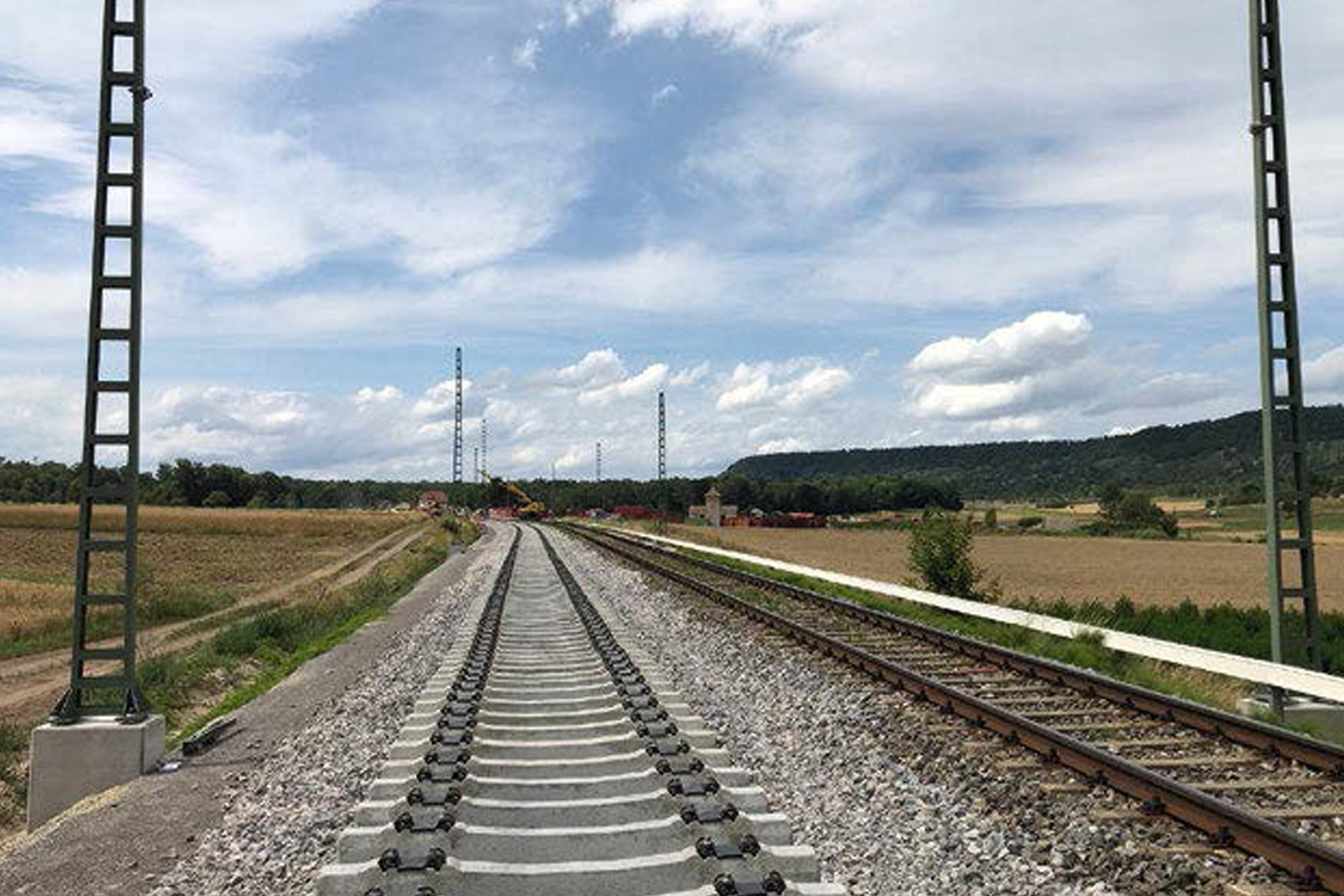
The rail network of the railroads in Germany currently has a line length of around 38,500 km, of which around 60 % are electrified, i.e. equipped with an overhead line and thus suitable for the operation of electric locomotives. The federal and state governments are pursuing the goal of this proportion rising steadily to at least 70% by 2025. Assuming that the line length is fully maintained by then, overhead lines will have to be installed along 3850 km of railroad track over the next five years to achieve this goal. This includes the installation of 65,000 masts that will be needed to hang the overhead lines from. In off-rail construction projects, ductile iron piles have been part of the portfolio of numerous construction companies for several decades. And for good reason, since they offer a genuine economic alternative for quality-conscious builders. For the electrification of the Ammertalbahn between Tübingen and Herrenberg, ductile driven piles have now been used on a large scale for the deep foundation of overhead line masts along the 110-year-old railroad line.
Overhead contact line mats and traditional foundation types
Overhead contact line masts differ in terms of their function (supporting poles and guyed poles), in terms of the material (steel masts and concrete masts) and in terms of their connection to the foundation (top-mounted masts, insertion masts and top-girder masts). While concrete masts are generally used as inverted or inserted masts, steel masts are often built as top-mounted masts. In this case, the mast bases are bolted with anchor bolts that have previously been embedded and fixed in the foundation. Depending on the load, the number of anchor bolts used varies between four and 16 per mast. Within the steel masts, a distinction is made between
- the frame flat mast (flat mast for short), which consists of two U-profiles connected by binding plates, which are welded onto mast base plates. Profiles with dimensions of 100, 120, 140 or 160 mm are commonly used.
- the angle mast (also lattice mast), which consists of four angle sections welded together by means of diagonal braces. The angle sections range in size from 80 x 8 mm to 150 x 14 mm, depending on length and load. The mast bases vary in dimensions from 600 x 800 mm up to 1600 x 2000 mm.
- the double-T mast, which is only used by Deutsche Bahn AG (DB) in exceptional cases, e.g. as a supporting mast within integrated noise barriers.
What they all have in common is the task of withstanding the forces acting on them and transmitting them to the foundation and the footing. These forces result from the weight of the catenary, from tensile forces with which the catenary is re-tensioned, from wind forces and from aerodynamic loads. Additional forces are introduced by other lines mounted directly on the mast or on trusses. The foundations of the catenary masts have the task of transferring all forces of the catenary system into the ground. The selection of the respective foundation types is essentially determined by:
- the soil mechanical properties of the subsoil,
- the load,
- the types of mast used,
- the technological conditions,
- the geometric boundary conditions and
- the costs
determined.
Pile driving
In Germany, pile-driven foundations have become established at pylon sites with low-lying load-bearing soil layers and/or high groundwater levels. In pile-driving foundations, steel sections or steel pipes are generally driven into the ground and then provided with a concrete head with embedded anchor bolts for the installation of the support pylons. The profiles used have various cross-sectional shapes and dimensions, and weights range between 50 and 500 kg/m. Depending on requirements, even heavier components are used. The design and construction of pile-driven foundations is set out in DB's Ebs drawing directory for standard overhead contact lines. It also contains guide values for the number of blows to be achieved with the pile-driving equipment in the load-bearing soil. If the client decides in favor of a pile-driven foundation, essential prerequisites must be met:
- the ground must be suitable for pile driving and load-bearing
- it must be possible to reliably dimension the pile-driving profile in advance.
This, in turn, presupposes that an appropriate site investigation has been carried out in accordance with DIN EN1997 and that equipment capable of handling and reliably installing even heavy pile-driven sections weighing several 1000 kg is available for the construction work. If, during driving, it is determined on the basis of the impact figures that the soil has a lower load-bearing capacity than assumed in the calculation, measures must be taken to ensure the stability of the piles. In practice, these measures always mean additional expenditure in the form of time and money. If one wants to reduce the risk of such a scenario occurring, it is worthwhile to weigh up the technical options and variants well and thoroughly. In particular, there is great potential in the deliberate selection of the foundation method. Instead of transferring the loads in a concentrated manner via a large, heavy pile-driving element, it is also possible in principle to divide the load and use several small, lightweight foundation elements. Ductile driven piles are a good choice for this purpose in rammed soil.
Driven pile system in theory and practice
Ductile driven piles, called prefabricated driven cast iron piles or ductile iron piles in EA Piles, were first used in Sweden in the early 1980s, but only for underpinning in buildings. In 1986, the ductile iron pile came to Austria, where it was developed by the company Tiroler Rohre GmbH in cooperation with Austrian and German specialist foundation engineering firms into the product as it is known today in Central Europe and beyond as a flexible and versatile foundation system. Cast iron with nodular graphite as the material gives the pile pipe high ductility and strength, thus enabling piles to be driven by powerful hydraulic hammers without the risk of overstressing. Industrial manufacturing combined with end-to-end quality control guarantee compliance with cross-section and material parameters, such as tensile strength ≥ 450 MPa and 0.2% yield strength ≥ 320 MPa. The pile segments are manufactured as centrifugally cast pipes in three diameters (98 mm, 118 mm and 170 mm) with different wall thicknesses. Conical sockets, which are cast in one go during pipe manufacture, allow easy joining of the 5 m long pipe segments. The high impact energy during driving results in a rigid, force-locked connection of the pile tubes. In this way, any pile lengths can be produced, adapted to the actual subsoil conditions encountered on site.
Installation
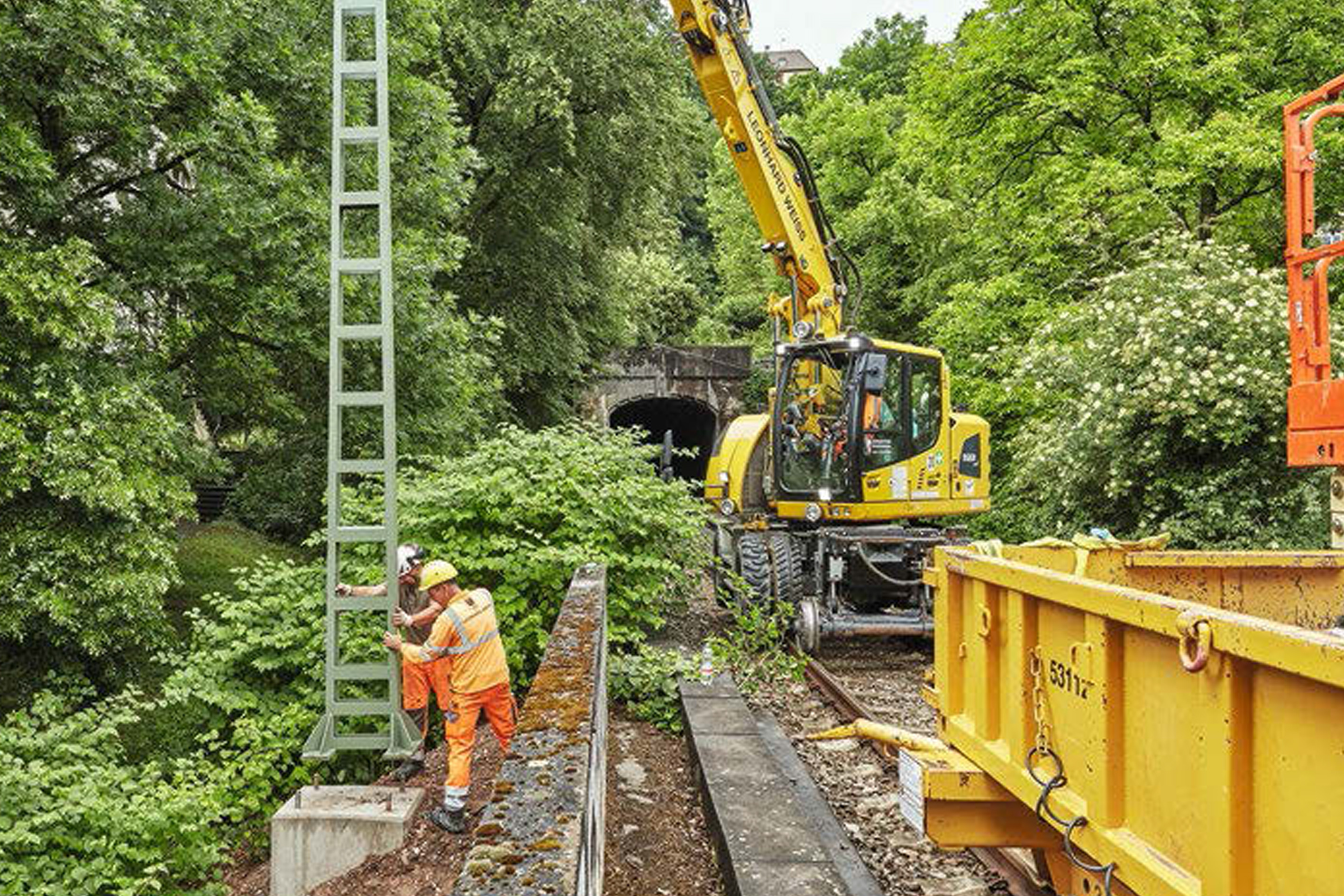
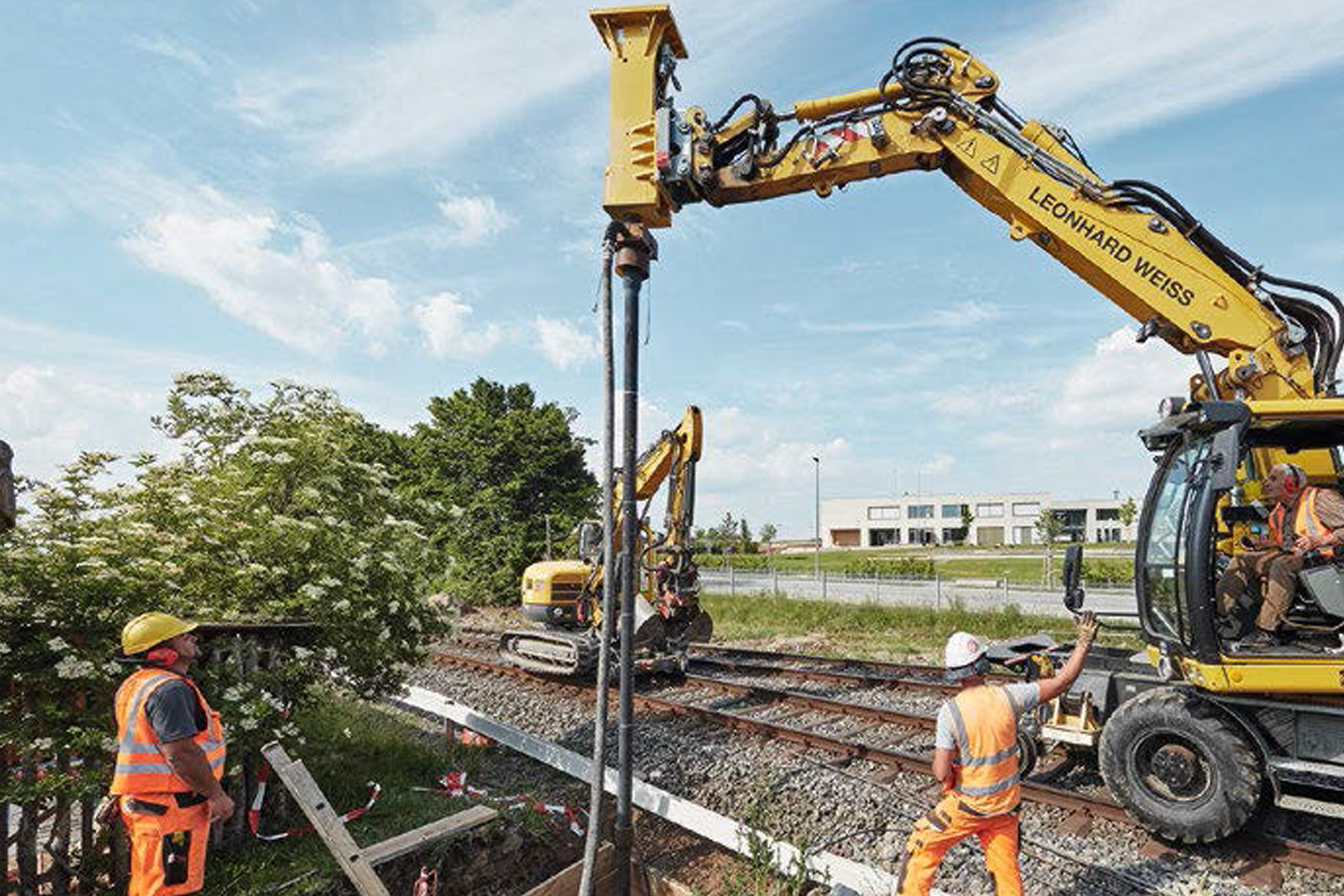
The manufacture of ductile iron piles is governed by DIN EN 12699 Execution of work in special civil engineering - Displacement piles. Supplementary details of execution can be found in the German approval Z-34.25.230 of the DIBt. Ductile iron piles can be designed with or without grouting. In the version without jacket grouting, the diameter of the pile shoe corresponds to the diameter of the first cast iron pipe (starter pipe). This type of pile is usually used as a stand-up pile on very firm ground (e.g. rock). The hollow core of the cast iron pipes is filled with cement mortar or concrete after the pile has been installed. For the design with jacket grouting, a pile shoe with a circumferential projection to the starter pipe of at least 40 mm is used. During the driving process, cement grout is permanently pumped through the hollow core of the ductile iron pipes to the pile foot and fills the annular space formed by the protruding pile shoe. This type of pile is typically used as a "floating" foundation in noncohesive and cohesive soils. When the pile has reached its final depth, the protruding pile shoe is cut off with an angle grinder and the pile is terminated with a pile head plate. These pile head plates are statically dimensioned for the maximum load-bearing capacities and ensure the frictional connection to the foundation above. The cut-off remnant is used as a starter pile during the next driving operation. The 5 m long, slender and relatively light pile tubes allow the use of maneuverable and commercially available equipment. What is needed is a standard excavator (from 20 t), a hydraulic hammer with a special hammer head suitable for the pile type and a concrete pump.
Design
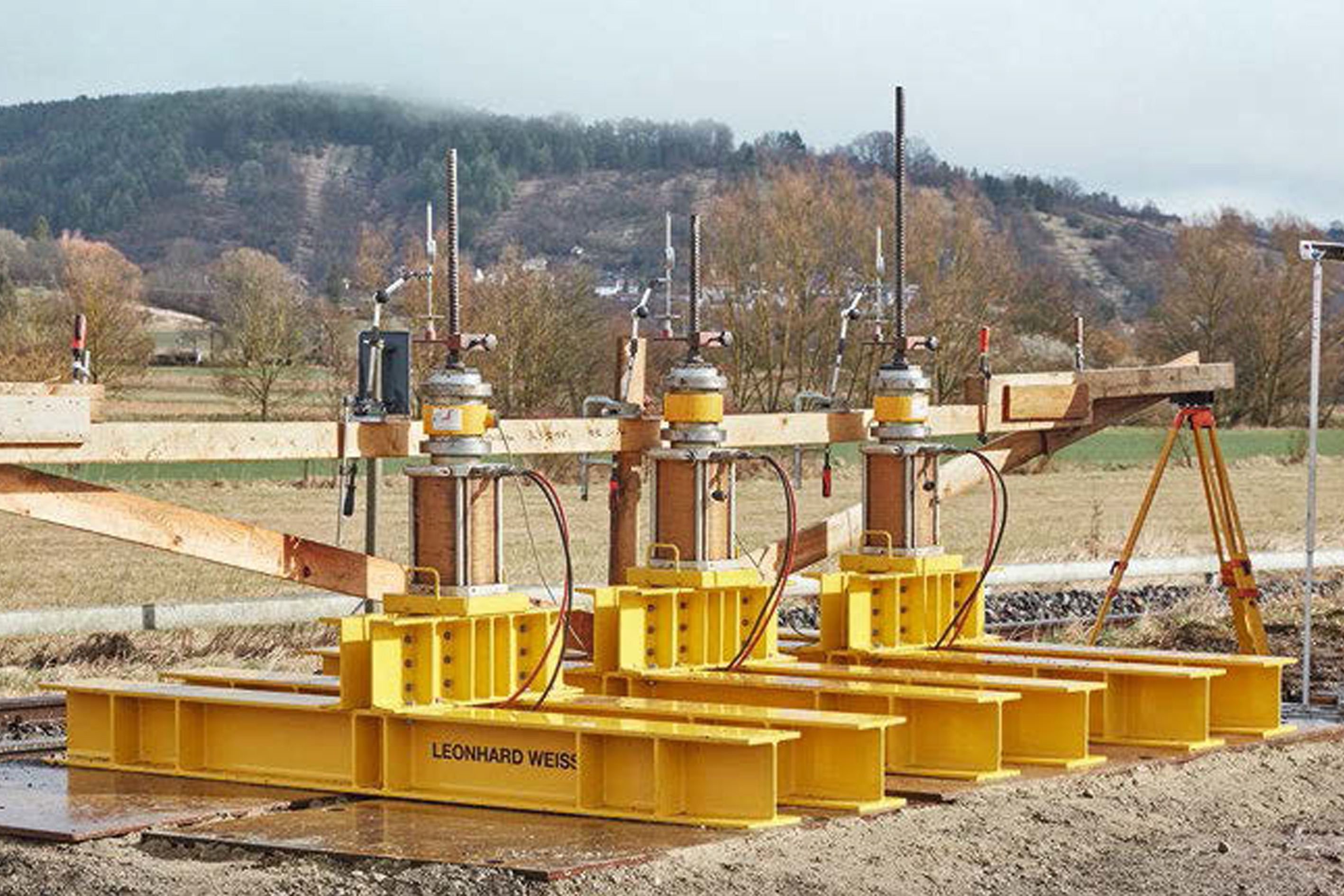
The design of driven ductile iron piles - in relation to their use as pressure piles - is described in the "Allgemeine bauaufsichtliche Zulassung Z-34.25.230" issued by the Deutsches Institut für Bautechnik (DIBt). At Point 3.2.2.2, the design values of the cross-sectional load-bearing capacity of piles are given in Table 4. Depending on the type of cast iron pipe, the cement mortar used and the type of pile (with / without grouting), the values vary between 450 kN and 2137 kN. Verification of the external load-bearing capacity is to be provided in accordance with Section 3.2.1 by means of test loads or determined on the basis of empirical values. EA-Pfähle states in Section 5.1 (5) that the empirical values should be derived from test loads. If empirical values are used, the values given in EA Piles for grouted piles (Tables 5.26, 5.27) are usually used. If test loads are carried out, static test loads are usually preferred. Dynamic test loads show comparable results, especially for non-cohesive soils, and can be used as a more cost-effective variant for the compaction of soil information, especially in large-scale projects. The usual practice regarding verification of the external bearing capacity depends on the size and conditions of the project and also on the respective wealth of experience of the special civil engineering company carrying out the work. The use of the driven ductile iron pile as a tension and alternating load pile has been common practice for many years and is now state of the art in Austria and Germany. Analogous to the micropiles described in EA Piles, Section 2.2.6, a steel support member is set in the still liquid cement mortar in the ductile iron pipe and then concreted into the foundation block with the statically required anchorage length. This ensures the connection between the pile and the foundation above, which is necessary to dissipate the tensile forces. In Austria, the piling system is approved as a compression, tension and alternating-load pile with BMK approval GZ 2020-0.094.414. In Germany, DIBt approval is at an advanced stage of processing; for projects with tension piles, the implementation planning is currently usually checked and approved by the test engineer.
Pile driving as additional ground investigation
Measuring and documenting the driving times per meter of pile driving, the so called "Rammaufnahme", is an important part of the production process. This "measured penetration resistance" enables the design assumptions to be checked, local, serious deviations from the underlying soil exploration to be identified, and enables the contractors to adjust the pile lengths directly to actual, locally different soil conditions encountered.
Ductile piles in the Ammer Valley
The Ammertal Railway connects the towns of Tübingen and Herrenberg, a good 20 km apart, to the south of Stuttgart. For the most part, it runs through the valley of the Ammer River, which not only gives its name to the line but has also decisively shaped the relief and the subsoil south of the Schönbuch for thousands of years. Thus, the railroad track runs partly in anemic valley deposits, partly in the layers of gypsum keuper, Lettenkeuper or loess loam. In the valley section, 13 m thick deposits were drilled: Alluvial loams followed by 30 cm to 4 m thick peat layers and clayey-silty talc. At the transition to the underlying Keuper, mostly a stiff to semi-solid weathering clay was explored. Only the latter, as well as the Keuper itself, are suitable for low-settlement load transfer under the overhead line pylons. The recommendation of the geotechnical expert was logically that, because of the subsoil conditions encountered, a foundation on ductile iron driven piles should be considered first and foremost. The client, the Zweckverband ÖPNV im Ammertal, followed both his subsoil expert and the recommendations of the relevant geotechnical codes and commissioned static pile test loads on ductile driven piles to determine the load-bearing properties. In consultation with the subsoil consultant, the overhead line designer, the foundation designer, and the contractor, three test sites were identified to represent the governing subsoil conditions. At each site, three test piles were installed in January 2020 and tested by the Institute of Geotechnical Engineering of the University of Stuttgart after a four-week rest period. The piles, nine in all, were made with TRM 118 / 9.0 mm ductile iron pipes (diameter 118 mm, wall thickness 9.0 mm) and tension members of B500B threaded steel D = 32 mm and grouted with cement mortar of strength class C 25/30. The test loads were carried out as tensile tests on three piles at a time, based on the standards manual EC 7, DIN 1054/A1: 2012-08 and EA-Piles: 2012 (System A). All piles could be loaded without any problems to the scheduled test force of 270 kN and then further to the maximum allowable test force of 350 kN. The measurement results show that all piles reached load-bearing ground, so that the maximum test force 350 kN could be applied with creep dimensions of maximum 0.68 mm and permanent displacements of maximum 3.48 mm. With proof that the tension member reinforced ductile iron piles met the requirements of the implementation planners, the test engineer and the subsoil, the design was completed and put into action between May and November 2020. Ductile driven piles were installed at 180 pylon locations, mostly from the track, using common two-way techniques. As predicted by the subsoil surveyor, the load-bearing soil layers were quite variable and were often only encountered beyond the 10 m mark. With the uncomplicated length adjustment of the ductile iron pipes and tension members, all the piles could be produced as the respective driving times immediately required.
Conclusion
According to their approval, the ductile iron piles are restricted to use as compression piles. However, if the cast iron pipe compression element is combined with an adjusted tension member, as described, for example, in EAPfähle Sec. 2.2.6, this provides a pile that is demonstrably capable of transferring compressive and tensile loads from the pylon foundations to (any) deep load-bearing soil layers. Unlike the usual driven foundations with heavy sectional girders or driven pipes, however, the ductile-drive piles can be installed from the track without any problems using standard 22-ton class two-way excavators. With the recording of the driving times in relation to the installation depth, the contractor gets the guarantee for each individual pile that it has reached the required embedment depth in the load-bearing subsoil - even if the subsoil investigation in advance was limited to a preliminary investigation with a large investigation grid.
Authors: DI Uwe BURKHARDT and Bmstr. DI Bernhard SCHRÖTTER
With friendly permission of "Der Eisenbahningenier", International Journal for Rail Transport and Technology, www.eurailpress.de/ei